



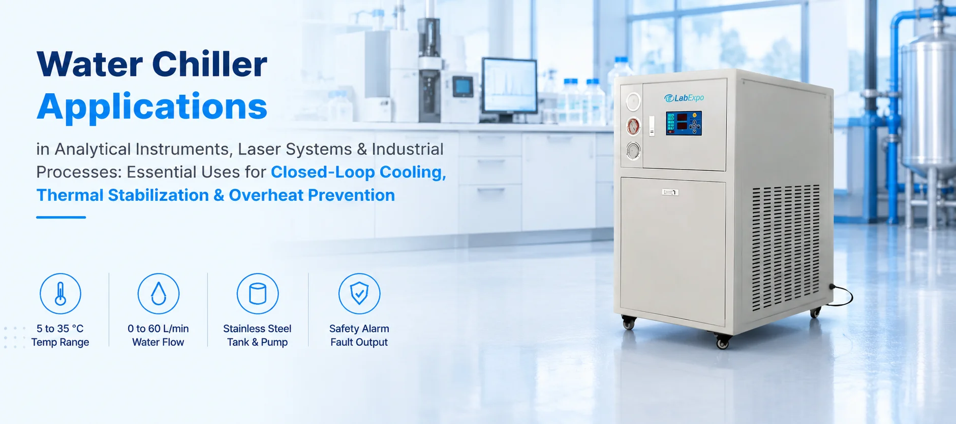
Instruments that run hot drift, shut down or fail early, and tap water cooling wastes water while swinging with the season. A chiller removes heat into a closed loop and holds the supply temperature steady. This guide explains how the loop works, where it is used, how to size flow against heat load, and which selection mistakes to avoid.
Why Heat Removal Needs Control
Lasers, detectors, vacuum pumps and reactors turn part of their input power into heat. If that heat is not removed, performance changes first and hardware damage follows. A laboratory water chiller prevents this by supplying liquid at a set temperature in a closed loop, so the same liquid is cooled and reused rather than drained.
The Water Chiller 29-WCR104 listing describes a 5 °C to 35 °C temperature range, a 37 L stainless steel tank, a flow of 0 to 60 L/min and a digital display.
How the Closed Loop Works
A water chiller machine combines a refrigeration circuit with a pump and a tank. The sequence below follows one full circuit of the liquid.
- 1
Heat is picked up
Cool liquid flows through the instrument jacket or plate, and warms as it absorbs heat.
- 2
Return to the tank
The warm liquid returns to the reservoir. The listing gives a 37 L stainless steel tank.
- 3
Heat is rejected
The refrigeration circuit moves that heat out of the liquid and releases it to the surrounding air.
- 4
Temperature is held
A controller compares the liquid temperature with the setpoint and adjusts cooling. The listed range is 5 °C to 35 °C.
- 5
Liquid is pumped out
The integrated pump sends cooled liquid back to the load. The listing gives 0 to 60 L/min and an outlet pressure of 0 to 2 kgf/cm².
- 6
Faults are flagged
The page lists a safety alarm and a fault signal output for connection to an external system.
A water cooling chiller differs from a plain water cooling system because it can cool below room temperature. A simple water cooling unit using tap water can only get as cold as its supply, which varies with the season. The closed loop also protects instrument channels from scale and contamination, since the same treated liquid circulates.
Where Chillers Are Used: Instruments, Lasers and Processes
The product page lists five areas of use. Laboratory cooling equipment of this type serves any device where steady temperature affects the result.
Analytical instruments
Detectors, spectrometer sources and similar equipment hold calibration better when their coolant stays at one temperature.
Laser systems
Laser heads shed most of their input power as heat, and wavelength and output can drift when the head warms.
Biotechnology processing
Jacketed vessels and reaction steps use a circulating coolant to hold set temperatures during a run.
Automotive testing and packaging lines
Test rigs and continuous lines remove process heat so parts and seals stay in range.
An industrial water chiller and a process water chiller work on the same principle as a bench unit. The difference is mostly scale, with larger capacity, higher flow and heavier-duty pumps. Hospital and research laboratories use chillers where imaging, analysis or sterilization equipment needs a steady cooling supply.
Chilled Loop, Tap Water and Air Cooling Compared
The right cooling method depends on the heat load, the target temperature and the space. The table gives typical differences.
| Method | Temperature control | Typical limit |
|---|---|---|
| Tap water cooling | Follows the supply, so it varies by season | Cannot go below supply temperature and uses large amounts of water |
| Air cooling alone | Limited by room temperature | Struggles with high heat load in warm rooms |
| Recirculating chiller | Controlled, usually for smaller loads | Capacity and flow suit benchtop instruments |
| Water chiller | Controlled, with a larger tank and higher flow | Needs floor space, power and room for heat rejection |
For a quick overview of how these types are grouped, the chiller category shows each type side by side.
Heat Load, Flow and Temperature Rise: A Worked Example
The liquid carries heat away according to a simple relation: heat equals mass flow, times specific heat, times temperature rise. The table assumes a 2 kW heat load, water as the coolant and no losses. The figures are illustrative.
| Flow | Calculation | Temperature rise across the load |
|---|---|---|
| 5 L/min | 2,000 ÷ (0.0833 × 4,186) | about 5.7 K |
| 10 L/min | 2,000 ÷ (0.1667 × 4,186) | about 2.9 K |
| 20 L/min | 2,000 ÷ (0.3333 × 4,186) | about 1.4 K |
| 40 L/min | 2,000 ÷ (0.6667 × 4,186) | about 0.7 K |
| 60 L/min | 2,000 ÷ (1.0 × 4,186) | about 0.5 K |
Higher flow keeps the temperature rise smaller, but the instrument has its own limits on flow and pressure, so more is not always better. The listed 3 kW capacity leaves headroom over a 2 kW load, though the page gives no capacity curve, so capacity at a given setpoint and room temperature should be confirmed with the supplier.
Tank Volume and Overheat Prevention
The tank acts as a thermal buffer. When the heat load exceeds what the chiller can remove, or the chiller stops, the stored liquid absorbs the difference and buys time before alarms and shutdowns matter.
| Item | Calculation | Result |
|---|---|---|
| Heat stored per kelvin | 37 kg × 4,186 J/kg·K | about 155 kJ per K |
| Warming rate, chiller off, 2 kW load | 2,000 W ÷ 155,000 J/K | about 0.77 K per minute |
| Time to rise by 10 K | 10 ÷ 0.77 | about 13 minutes |
The result is a rough upper bound on warning time, since the pipes, instrument and metal tank add a little thermal mass and the instrument itself also warms. It shows why a small reservoir leaves little time to react, and why the alarm and fault signal output matter on unattended runs.
Installation and Daily Operation
Good placement and simple routines extend the life of a chiller and keep the loop stable.
- Leave clearance around the cabinet so heat can leave the condenser, and keep the room ventilated.
- Use clean hoses of suitable length, and keep runs short to limit pressure loss.
- Fill the tank with the coolant the instrument maker specifies, often distilled or deionized water, and add inhibitors if the loop contains mixed metals.
- Set the target temperature above the room dew point to avoid condensation on cold lines and instrument surfaces.
- Check the flow and pressure readings against the instrument manual before long runs.
- Connect the fault signal output to the instrument or a building alarm if the run is unattended.
- Inspect the tank level, filter and condenser regularly, and clean dust from the condenser fins.
Specifications Worth Reading Closely
The values below come from the 29-WCR104 listing, also available in its product catalog. The second table shows details the page leaves out.
| Parameter | 29-WCR104 listing | Why it matters |
|---|---|---|
| Temperature range | 5 °C to 35 °C | Sets which loads can be matched |
| Refrigeration capacity | 3 kW (printed as 3 kW/h) | Should exceed the heat load with a margin |
| Power | 1500 W | Determines the supply and circuit needed |
| Tank | 37 L, stainless steel | Provides thermal buffer and refill interval |
| Flow | 0 to 60 L/min | Must fit the instrument flow window |
| Outlet pressure | 0 to 2 kgf/cm² | Must stay within the load's pressure limit |
| Dimensions | 650 x 650 x 1050 mm | Defines floor space and doorway access |
| Display and alarms | Digital display, safety alarm, fault signal output | Supports monitoring and unattended runs |
| Not stated on the page | Why a buyer needs it |
|---|---|
| Temperature stability value | Decides suitability for sensitive instruments |
| Refrigerant type | Affects service and regulatory handling |
| Pump head | Shows whether the flow holds through long or narrow lines |
| Weight and noise level | Affects placement and the working environment |
| Capacity at different setpoints and room temperatures | Capacity usually falls as ambient temperature rises |
| Supply voltage and phase | Needed to prepare the power connection |
Selection Mistakes to Avoid
- Sizing to the exact heat load. A margin is needed for startup peaks, warm rooms and future equipment.
- Reading capacity as a fixed figure. It changes with setpoint and ambient temperature.
- Ignoring flow and pressure. The instrument may need a narrower window than the pump can deliver.
- Choosing a very small tank. Less liquid means less time to react to a fault.
- Skipping coolant quality. Poor water causes scale, corrosion and clogged channels.
- Forgetting room heat. A chiller releases heat to the room, so ventilation matters.
- Overlooking alarm connections. A fault signal is only useful if something is listening to it.
Exploring the Wider Chiller Range
This unit belongs to the chiller group at Lab Expo, where the full range of chillers is divided into water chillers, air cooled chillers and recirculating chillers. The water chiller group lists many models, including 29-WCR103 and 29-WCR105.
The category page describes compressor-driven units for laboratory, research and industrial use, with adjustable temperature and flow, corrosion-resistant tanks and pumps, digital monitoring and integrated fault alarms. Buyers usually compare capacity against heat load, temperature range and stability, flow and pressure, tank volume, footprint and noise, and the alarm and control options.